Solar Racking Design:
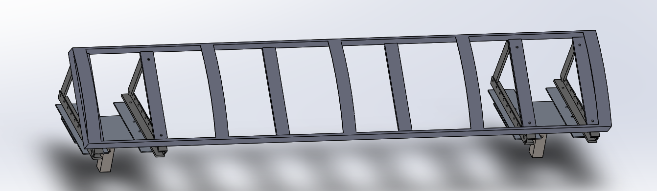
New changes were made after last week's discussion. The track team expressed doubts of welding. In order to alleviate any extra burden on welding the solar racks, the design was changed so that the ribs could be bolted into place. This new idea was explored with the manufacturing team as the ribs will be produced by Kevin.
A clamp created to sandwich the solar panel between the clamp and ribs. The clamp are adjustable and uses the same hardware to bolt down the ribs onto the rack. Rubber inserts will be placed between the clamp and solar panel to prevent damages while promoting clamping force.
There are still a few minor tweaks that will be needed implemented to finalize the Solidwork design. The design should be completed this week.
Procurement:
A new connector for the modified 4 cell batteries were decided with the Controls team. 11 sets of connectors were order for bogies, charging modules, and batteries. The new 4 cell batteries will need to be shrink wrapped. Proper sized shrink wrap will be purchased locally.
Wednesday, March 1, 2017
Wednesday, February 22, 2017
Week 3 Project Update
Design:
With the design approval, calculations of required amount of materials were established. The quantities of aluminum stock was communicated with the track team. Currently, waiting for a response to determine if more material needs to be purchased from Coastal Aluminum. Confirmed with the track improvement team that the ribs will need to be fabricated according to previously mentioned specifications. Measurement of charging components and supporting hinged box were made to create a Solidwork design. The solar rack design still needs minor improvements to the mating of the two separate pieces before completion.
Procurement/Fabrication:
Position locking draw slider was purchased to match the physical dimensions of the solar rack and charging components. I am hoping to have all designs finalized by the first presentation. With that part complete, fabrication of components can begin that weekend.
T-bar:
A new idea of the modifying the supports proposed to the track team. An additional clamping plate between the T-bar and the 3-bar linkage can shift of the weight of the rack further in towards the center or outer perimeter of track loop to help with any stability issues.
With the design approval, calculations of required amount of materials were established. The quantities of aluminum stock was communicated with the track team. Currently, waiting for a response to determine if more material needs to be purchased from Coastal Aluminum. Confirmed with the track improvement team that the ribs will need to be fabricated according to previously mentioned specifications. Measurement of charging components and supporting hinged box were made to create a Solidwork design. The solar rack design still needs minor improvements to the mating of the two separate pieces before completion.
Procurement/Fabrication:
Position locking draw slider was purchased to match the physical dimensions of the solar rack and charging components. I am hoping to have all designs finalized by the first presentation. With that part complete, fabrication of components can begin that weekend.
T-bar:
A new idea of the modifying the supports proposed to the track team. An additional clamping plate between the T-bar and the 3-bar linkage can shift of the weight of the rack further in towards the center or outer perimeter of track loop to help with any stability issues.
Monday, February 13, 2017
Week 2 Updates
This week, I was able to charge a battery fully to determine the maximum voltage.
The initial voltage of the battery was 7.44 V.
The maximum voltage of the battery was 8.59 V after 67 minutes of charging. Further charging did not increase the voltage reading of the battery.
Several issues were discussed with the track manufacturing team:
- Ribs for the solar rack: arc length, radius, amount of pieces
- Modifications to the T-bar pole mount to allow adjustment of positioning
- Available materials left over
The controls team was informed of the battery that will be used to power the bogies. A battery was given to Chris, who has a charger, to test the controls using the rechargeable battery. Several more will be given to Luis for backup.
The bogie team was also informed of the battery size. The position of the battery will be inside the cabin.
The design of the solar panel rack begun. Measurements and dimensions of the pieces forming the rack were taken and imposed into SolidWorks. Previous year's T-bar pole mount was mated to the new rack.
A clamp system will need to be implemented to secure the solar panel onto the rack. The battery box design will need to be updated to a box design with a hinge.
Monday, February 6, 2017
Battery Charging Test
The objective for the first 2 weeks of this semester was to test charge the batteries and ensure functionality. Due to weather conditions being rainy and cloudy generally throughout the past 2 weeks, the only window I've found to test the equipment was on Saturday and Sunday. First, I began by checking the voltage of the combined 6 cell battery. The battery's initial voltage was 7.56V.
After about roughly 3 hours with numerous resetting of the charging unit, the voltage of the battery was 8.10 V. These resets were caused by dense clouds or other obstacles preventing the solar cells from producing enough power which results in a voltage drop across the circuit. Due to these resets, the time period of charging is unknown. Future plans will feature a recording device so that the exact time when charging stops will be known. The specifications for the iMAXB6AC states the allowable DC input voltage is 11-18V. The buck converter was set to 17.9V, the highest allowable voltage output (input into iMAXB6AC) to delay the "DC IN TOO LOW" error message which stops the charging process because of the insufficient sun light. According to the manual this error is caused by the input voltage being less than 11V.
Without any battery voltage charge chart, it is difficult to determine the state of charge (SoC) of the battery as the relationship between voltage and SoC is exponential. Only references I found for 7.2V nominal batteries were stating that a fully charged battery would measure ~8.4V. The goal of the next testing session is to determine the maximum voltage the batteries will reach and time it takes to reach this maximum voltage.
Thursday, January 19, 2017
Solutions to Mounting Batteries
A simple and low cost solution to mount the battery packs to the board containing charging components is to use Velcro straps. With cuts on the sides of a rectangular retaining box for the strap to loop around, the battery will be in locked position with minimum movement.
This design uses a locking latch along with a hinge to form a door that could be closed and opened. An enclosure underneath the board keeps the battery in place while allowing access from above.
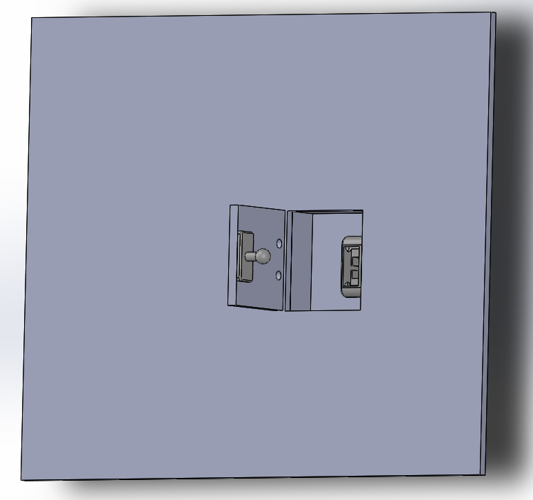
Similar to the design above, the battery pack is housed in an enclosure with an access door. The door is held closed using a push latch. The latch clamps down on the ball mounted onto the door when force is applied. The latch releases ball also with the application of force. This design will give the board a flush look with much of bulk placed behind the board.
Saturday, January 14, 2017
After noticing unistruts used to secured electrical wiring, this design was created. An unistrut is utilized on each side. The board is mounted onto two trolleys with 4 3/8 bolts and nuts. The unistruts will be mounted to the solar frame in similar fashion.
This design uses a pair of side mount drawer slide to mount the board containing the solar charging components. The biggest advantage of using side mounted drawer slide will be the two locking positions offered. The wheels are locked into place in the fully extended and fully closed positions. These rails are available off the shelf with different lengths.
Sunday, January 8, 2017
A bottom mounted drawer slide is used to provide the linear motion of the board containing the charging components. The slide is attached to a pair of brackets which are mounted directly to the solar rack. Each pair of bracket consist of 2 corner brackets and 3 pieces of aluminum rails. The corner brackets and aluminum rails are joined together with #8 screws. The slider, board, and brackets are joined together with #6 screws. The dimensions of the aluminum rails are the same dimensions of the upper rail of the track.

A similar design utilizing side mounted drawer slides is being worked on.
Subscribe to:
Posts (Atom)